Project Management
Directly from Customer's requests or specification, our own specification document is drawn up.
We also gather all the technical data and literature available that may be useful for the project.
Pre-design is carried out. Hardware, software, mechanical and workflow sketches. Discuss future implications.
Here's where dealbreakers are easy to solve.
Tasks flow creation. Kan-ban metodology using Trello, MS Planner or equivalent.
Design time estimation. Quotations for the most expensive components.
Work flow estimation. Gantt graph organization.
Final offer for client.
Design, calculations, simulations. Document it.
Capture SCH, design PCB, standardized control. Software design. Document it.
Prototype, testing, benchmarking. Corrections. Document it.
Product EMC certifications. MTBF, product cycle. Document it.
CAD files: mechanical, gerber, firmware. Assembly manuals. Packaging.
BOM files: product structure BOM, list of suppliers, MPNs & SKUs, purchase orders.
Quality: Testing manuals and Procedures, fixtures and test software.
Marketing & Customer docs: Product brief. User manual, product datasheet.
Project and product KPI's.
Lessons Learned. Improvement oportunities.





Hardware Design
A strict design procedure is followed. All the steps are procedural, this way we can evaluate the design procedure itself and improve it.
Not all designs are the same, the procedure is flexible enough to adapt to any project.
All projects can provide reusable blocks for other projects and save design time. This a key action. Every repetitive action is automated. Every piece of knowledge is reused.
Everything is documented.
- Design
- Simulation
- SCH
- PCB
- MNF DOCs
- Testing
Hardware Design and Design procedure Documents
The hardware design document is made throughout the design.
Every thought about the design, every decision, every dealbreaker is collected there.

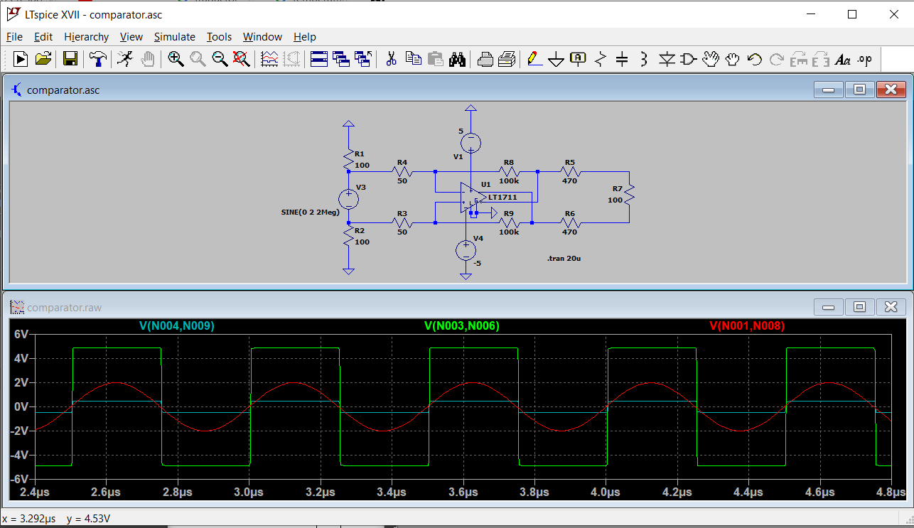
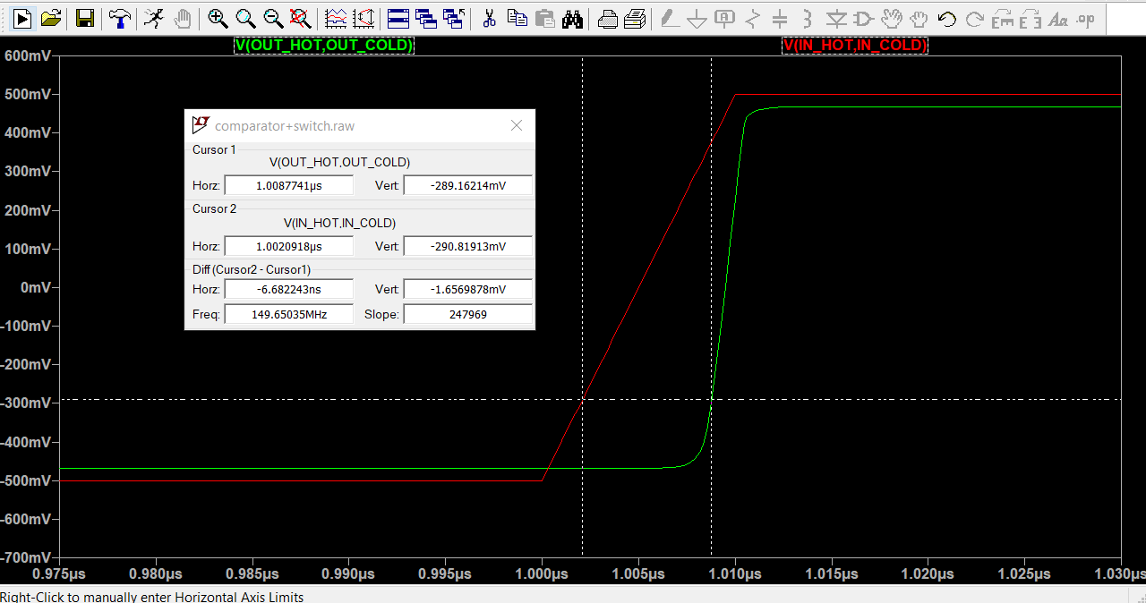
LT Spice simulation and Component models
Simulations of critical components, hysteresis and response times are performed.

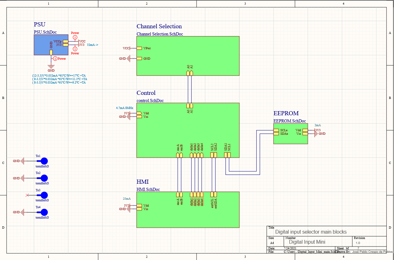
Snapshots from Altium capture Schematics
All components are divided between their symbol, their footprint and their information in DDBB for the BOM.
A main sheet is designed with a block layout. This hierarchical design allows you to simplify and reuse standard blocks.
Design rules and classes are used to ensure compliance with isolation and other design constraints.


SCH Design procedures and Quality Control Documents
A strict quality policy is followed in order to avoid errors and standarize work.
New components follow standard rules for drawing and DDBB insertion. A quality standard is available.
All schematics are drawn according to another quality standard.
An standardized control and quality checklist is available. It must be applied and filled for each design.
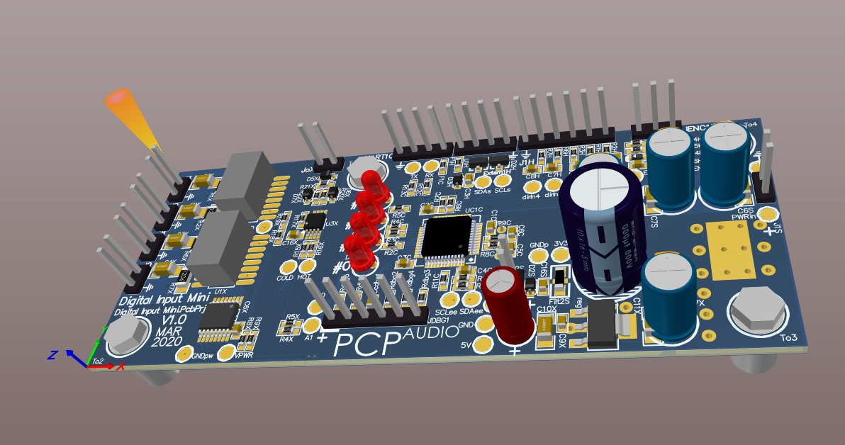
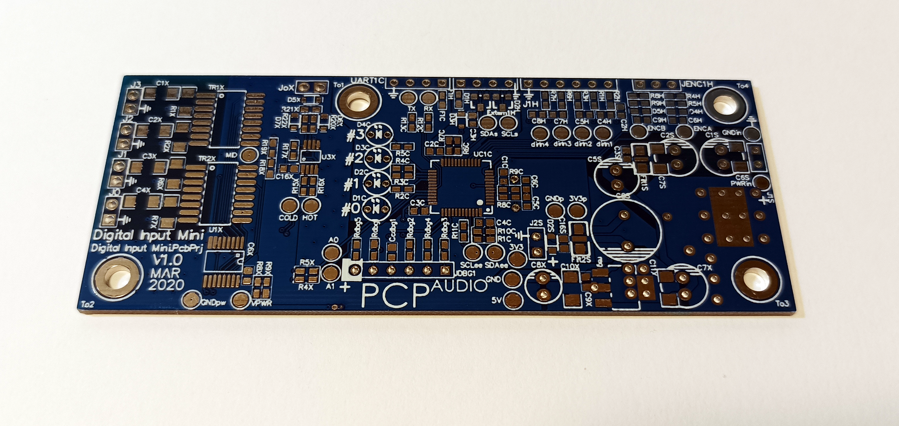
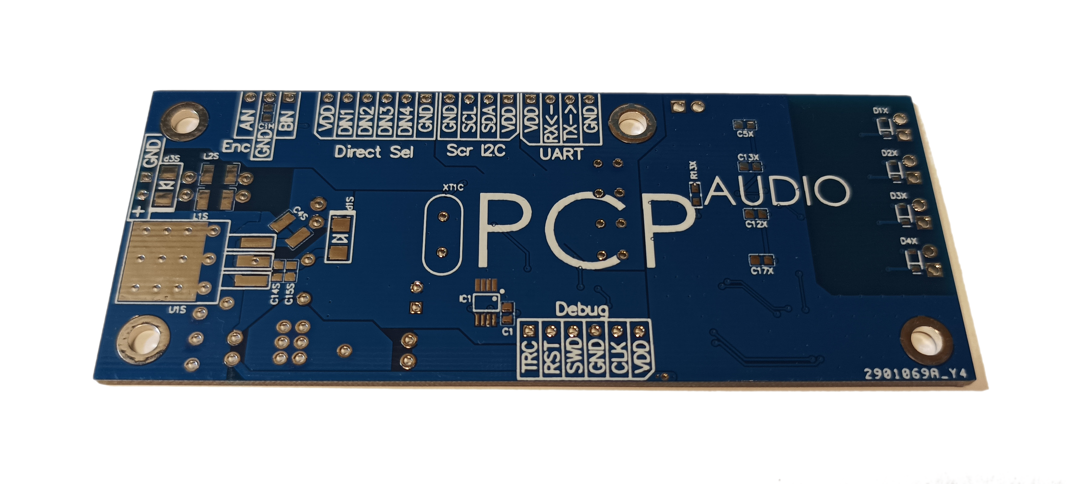
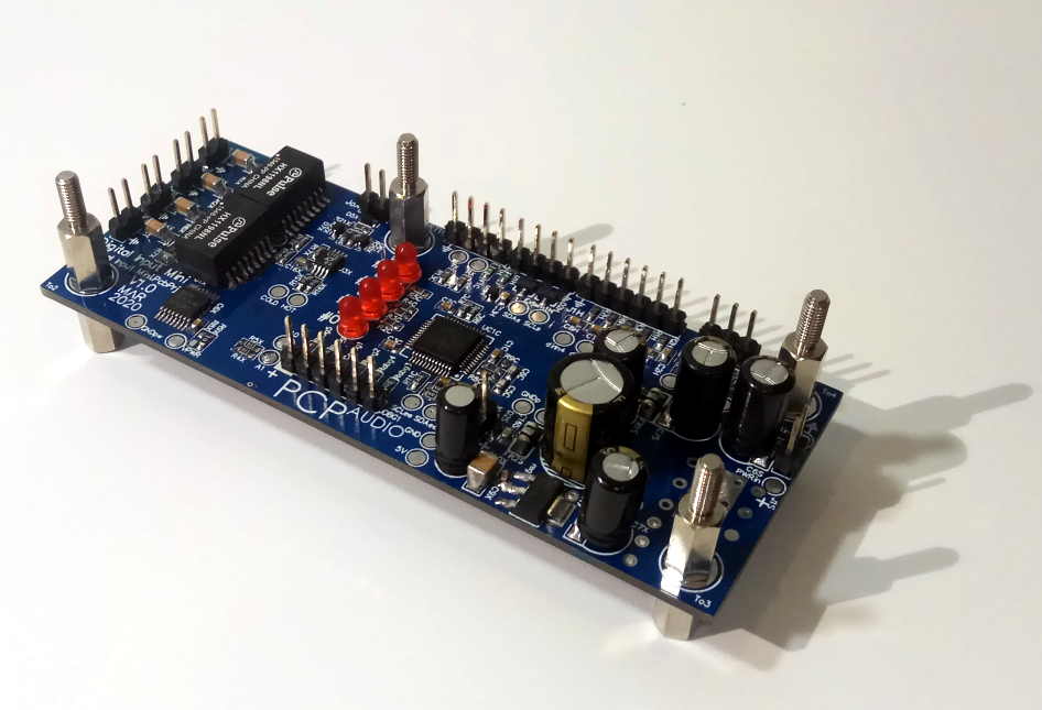
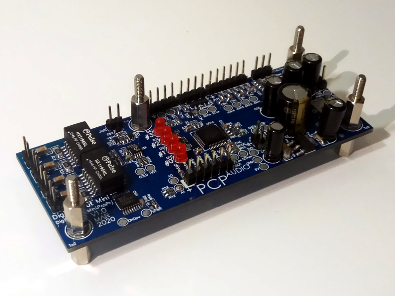
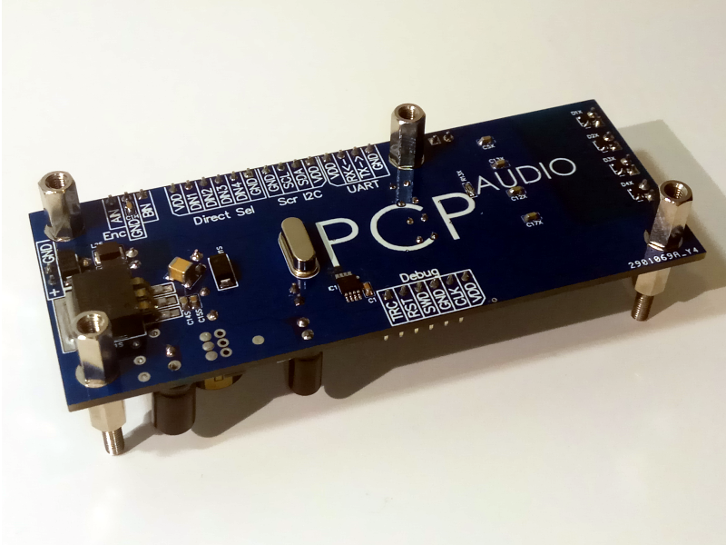
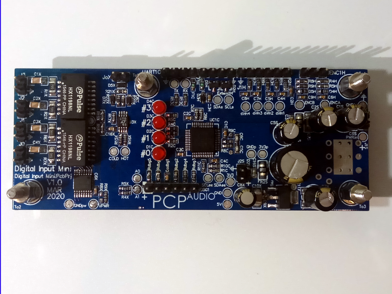
PCB Design and real PCB Snapshots
PCBs are designed by dumping the netlist created by the Schematics section, based on the available cut-out and the number of layers stated in the project specification document, with the footprints created for each package.
The width of traces is selected according to the requested power. Routing copper traces isn't just about connecting point A to point B, there are many electromagnetic phenomena associated, and is a key point for EMC compatibility.

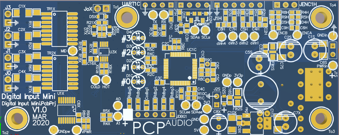
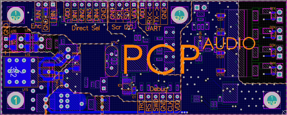
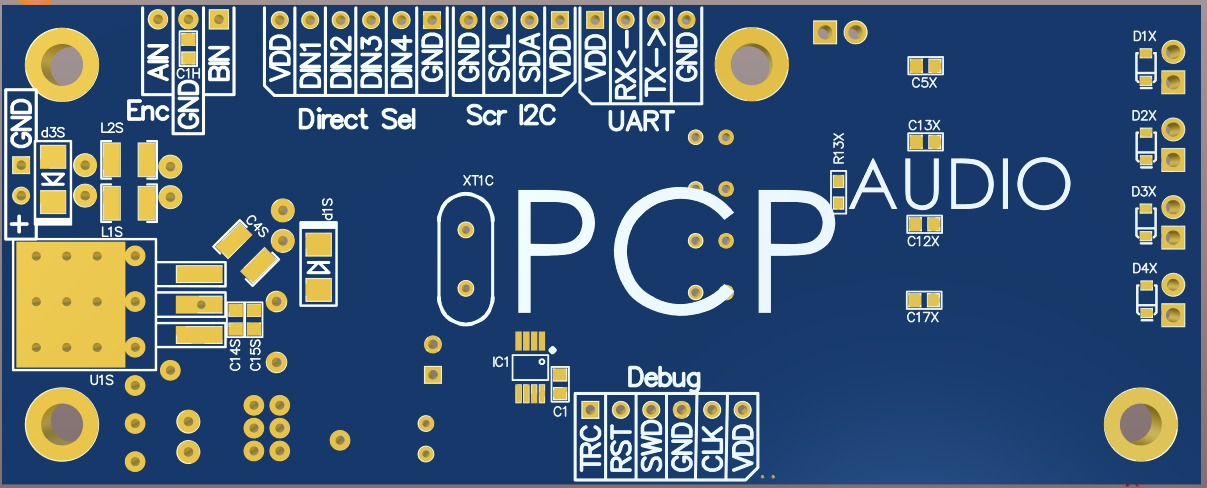
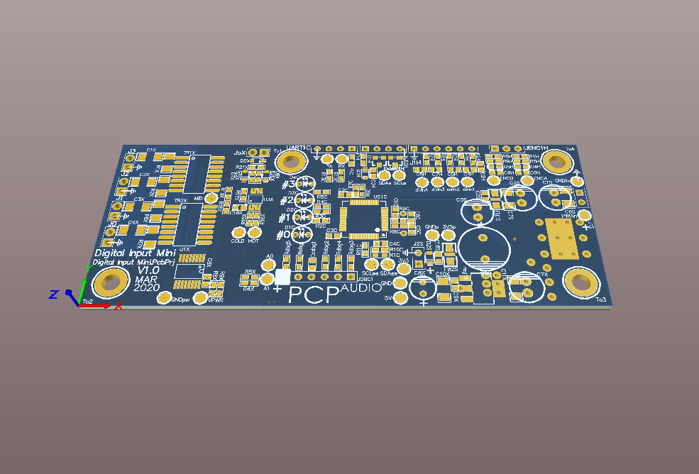
PCB Design procedures and Quality Control Documents
A strict quality policy is followed in order to avoid errors and standarize work.
All PCBs are designed uppon templates based on PCB manufacturer specifica classes.
All design follow design rules, allowing an automatic Design Rule Check (DRC). A quality standard is available.
Also, a standardized control and quality checklist is available. It must be applied and filled for each design.
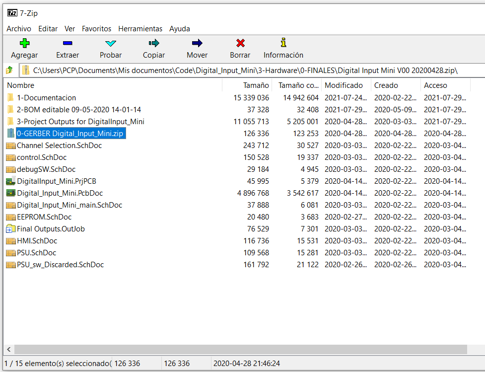
Manufacturing documents: Gerber, BOM, deliverables
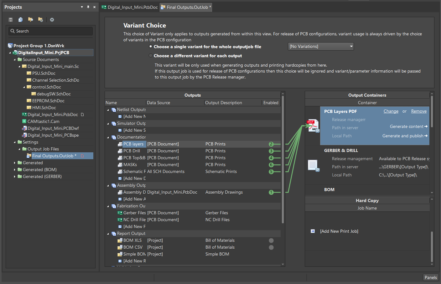
All the documentation necessary for manufacturing is generated automatically and standardized, with just a few mouse clicks.
That's done by using a properly-linked component database. Each component contents MPN info, prices, suplliers, Order Code(~SKUs) and equivalents.
Component info is gathered by API services from vendors and suppliers.
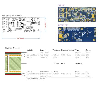
GERBER adn Pick Place files are generated by Altium Designer. Also, standardized Draftsman document templates, Schematics, PCB, variant mounting prints, an Excel BOM template with VBA macros complete the manufacturing info.

Testing: Snapshots and Documents
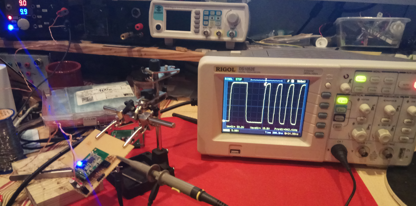
The Validation design test, and Manufacturing test are standardized by a template test document.
All validation steps are performed in an order that minimizes damage risk.
Testpoints are used to perform validation tests and In Circuit Testing (ICT).

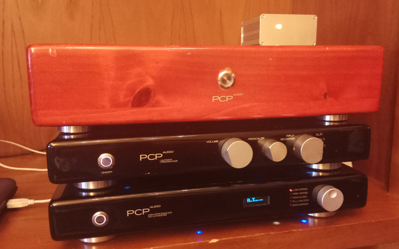

SOFTWARE design
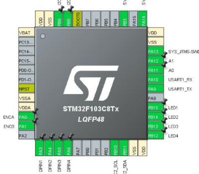
C coding for STM32 microcontrollers is done in a self-developed framework is developed for fast-coding.
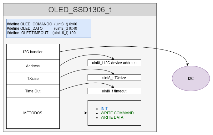
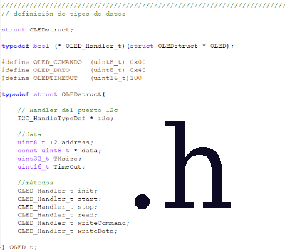
It emulates a class paradigm providing encapsulation and polymorphism, but not inheritance. Templates are used for every kind of file.
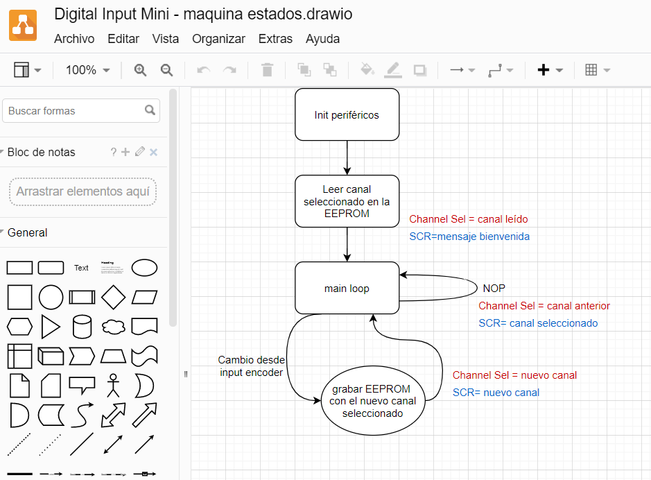
Driver -> Utility -> Application architecture is used. A finite state machine algorithm controls operation. Pseudo tasks run sequentially. EEPROM and Display writing are event executed.
Software Algorithm Design procedures
Think before acting.
Most of the software architecture is based directly on the hardware resources, as an input->processing->output machine. Algorithms are designed as a finite state machine, or written in pseudo-code before real coding.
The Software design document is made throughout the design.
Every thought about the design, every decision, every dealbreaker is collected there.
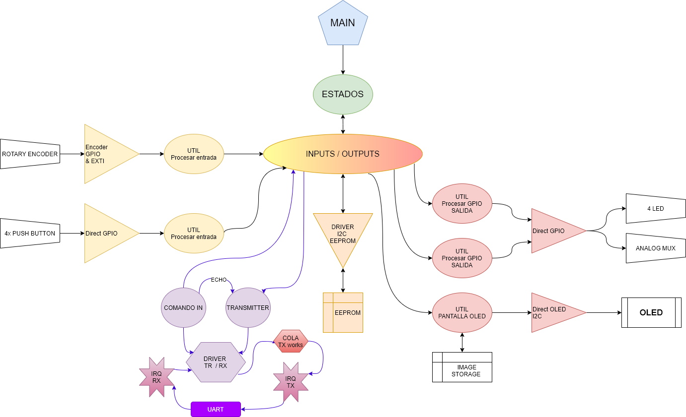
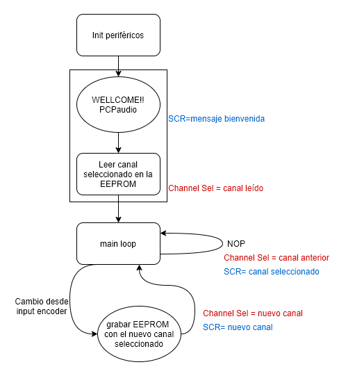
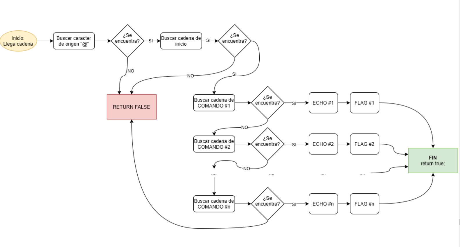
Driver Design, Driver -> Utility -> Application Architecture
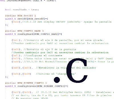
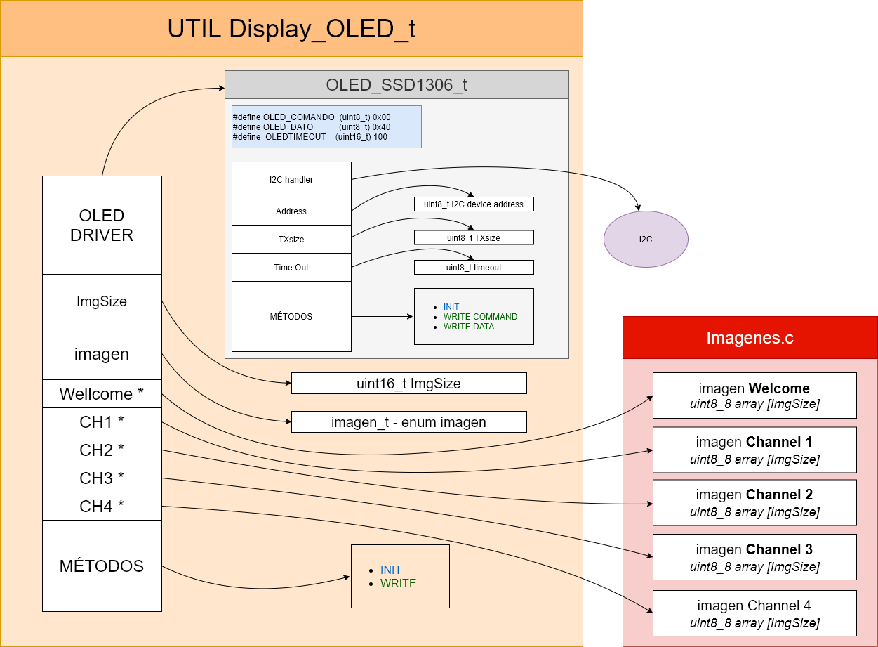
Drivers are designed based on the datasheet information. They are coded as classes and provide standard methods: Init/deinit, start/stop, read/write.
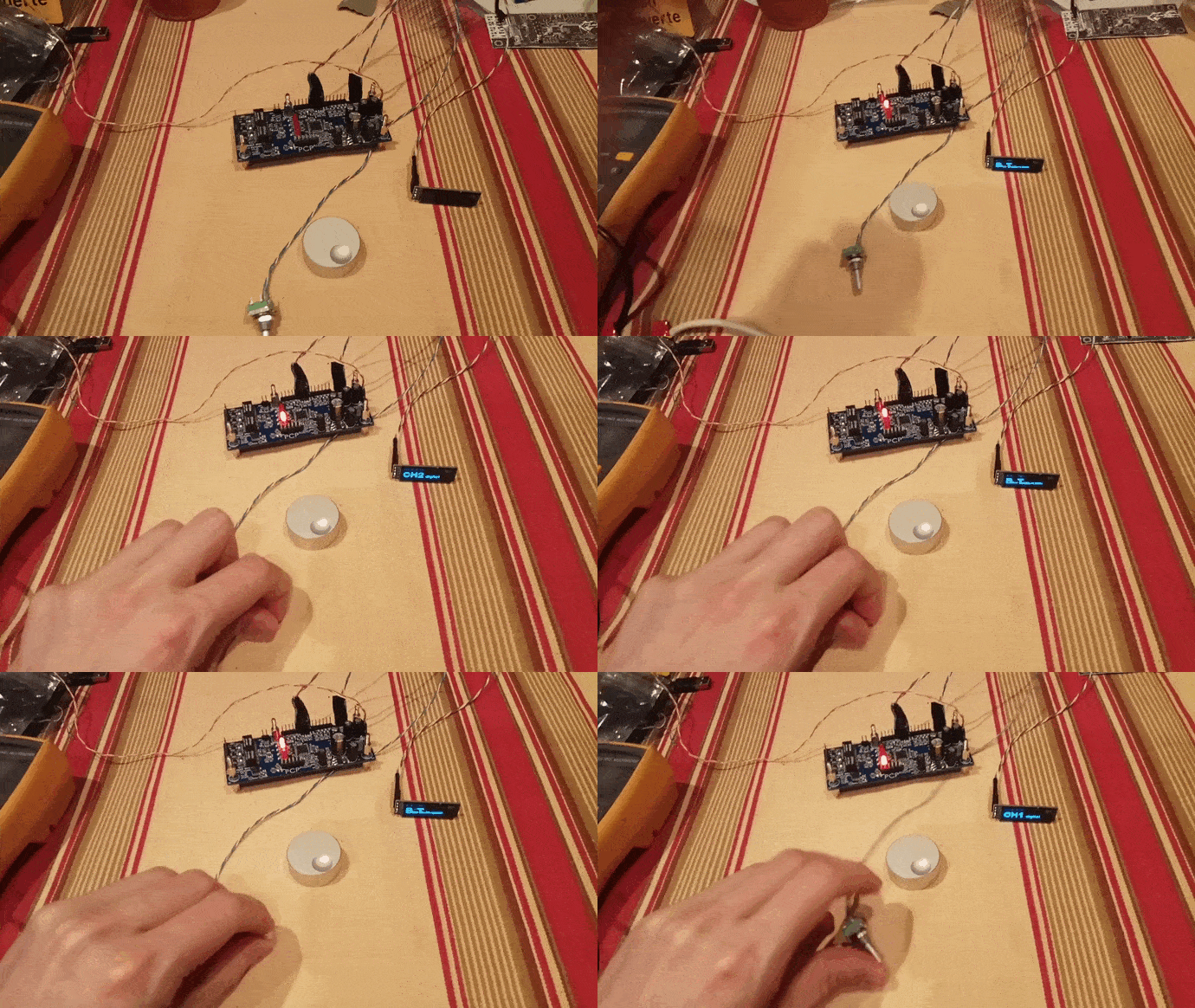
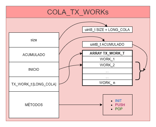
An example drive (OLED SSD1306 Display) is shown. Utility for Display, and MMI Output message queue structure are also shown.
Software Design, Standards and Quality Control Documents
A strict development policy is followed in order to avoid errors and standarize work.
An standardized control and quality checklist is available. It must be applied and filled for each design.